Showing posts with label amateur radio. Show all posts

Friday, May 1, 2015

NJIT's New Solar Telescope Unveils the Complex Dynamics of Sunspots' Dark Cores


Groundbreaking images of the Sun captured by scientists at NJIT’s Big Bear Solar Observatory (BBSO) give a first-ever detailed view of the interior structure of umbrae – the dark patches in the center of sunspots – revealing dynamic magnetic fields responsible for the plumes of plasma that emerge as bright dots interrupting their darkness. Their research is being presented this week at the first Triennial Earth-Sun Summit meeting between the American Astronomical Society’s Solar Physics Division and the American Geophysical Union’s Space Physics and Aeronomy section in Indianapolis, Ind.

The high-resolution images, taken through the observatory’s New Solar Telescope (NST), show the atmosphere above the umbrae to be finely structured, consisting of hot plasma intermixed with cool plasma jets as wide as 100 kilometers.
“We would describe these plasma flows as oscillating cool jets piercing the hot atmosphere. Until now, we didn’t know they existed.  While we have known for a long time that sunspots oscillate – moderate resolution telescopes show us dark shadows, or penumbral waves, moving across the umbra toward the edge of a sunspot – we can now begin to understand the underlying dynamics,” said Vasyl Yurchyshyn, a research professor of physics at NJIT and the lead author of two recent journal articles based on the NST observations.

Called spikes, the oscillating jets result from the penetration of magnetic and plasma waves from the Sun’s photosphere – the light-giving layer of its atmosphere – into the abutting chromosphere, which they reach by traveling outward along magnetic tubes that serve as energy conduits.  “This process can be likened to a blowhole at a rocky beach, where relentless onshore waves jet sea water high into the air,” Yurchyshyn said.

Sunspots are formed when strong magnetic fields rise up from the convection zone, a region beneath the photosphere that transfers energy from the interior of the Sun to its surface. At the surface, the magnetic fields concentrate into bundles, which prevent the hot rising plasma from reaching the surface. This energy deficit causes the magnetic bundles to cool down to temperatures about 1,000 degrees lower than their surroundings. They therefore appear darker against the hotter, brighter background.

“But the magnetic field is not a monolith and there are openings in the umbra from which plasma bursts out as lava does from a volcano’s side vents. These plumes create the bright, nearly circular patches we call umbral dots,” Yurchyshyn noted. “Sunspots that are very dark have strong magnetic fields and thus fewer openings.”

Compact groups of fast-changing sunspots create tension in their magnetic systems, which at some point erupt to relieve the stress. It is those eruptions that cause intense “space weather” events in the Earth’s magnetosphere affecting communications, power lines, and navigation systems.

“We had no sense of what happens inside an umbra until we were able to see it in the high-resolution images obtained with the world’s largest solar telescope. These data revealed to us unprecedented details of small-scale dynamics that appear to be similar in nature to what we see in other parts of the Sun,” Yurchyshyn said. “There is growing evidence that these dynamic events are responsible for the heating of coronal loops, seen in ultraviolet images as bright magnetic structures that jet out from the Sun’s surface. This is a solar puzzle we have yet to solve.”

Since it began operating in 2009, Big Bear’s NST has given scientists a closer look at sunspot umbrae, among other solar regions. It has also allowed them to measure the shape of chromospheric spectral lines, enabling scientists to probe solar conditions.

“These measurements tell us about the speed, temperature, and pressure of the plasma elements we are observing, as well as the strength and the direction of the solar magnetic fields,” said Yurchyshyn, who is also a distinguished scholar at the Korea Astronomy and Space Science Institute. “Thus we were able to find that spikes, or oscillating jets, are caused by chromospheric shocks, which are abrupt fluctuations in the magnetic field and plasma that constantly push plasma up along nearly the same magnetic channels.”

The study on umbral spikes was published in the Astrophysical Journal in 2014.

In a second paper published in the Astrophysical Journal in 2015, he is presenting another set of NST observations, taking a closer look at the sunspot oscillations that occur every three minutes and are thought to produce bright umbral flashes - emissions of plasma heated by shock waves.

The NST takes snapshots of the Sun every 10 seconds, which are then strung together as a video to reveal fast-evolving small explosions, plasma flows and the movement of magnetic fields. “We were able to obtain photographs of these flashes of unique clarity that allowed us to follow their development inside the umbra,” he said. Previously believed to be diffuse patches randomly distributed over the umbra, the researchers found their location is in fact not random. They mainly form along so-called sunspot umbral light bridges, which are very large openings in the sunspot magnetic fields that often split an umbra into two or more parts.

“Even more importantly, we found that umbral flash lanes tend to appear on the side of light bridges that face the center of the sunspot,” he added. “This finding is significant because it indicates that sunspot oscillations may be driven by one energy source located under the umbra. There are simulations that appear to reproduce what we have observed, which is very encouraging. We, as a community, are finally in the position to be able to directly compare the observations and the state-of-the-art simulation results, which is the key to making further progress in our field.”

To view more images, click here.

For further information, contact Tracey Regan at NJIT at tregan@njit.edu or 201-388-0232 or Craig DeForest, AAS/SPD press officer, at deforest@boulder.swri.edu or 303-641-5769.

Wednesday, April 29, 2015

Ham radio attempts to fill communication gaps in Nepal rescue effort

A nice write-up outlining how Ham Radio has once again provided vital lifelines of communication to the people of Nepal.

Amateur radio has stepped in to fill communication gaps in Nepal, which is struggling with power outages and a flaky Internet after a devastating earthquake on Saturday killed over 5,000 people. Though 99 persons have ham licenses in Kathmandu, about eight use high-frequency (HF) radios that can transmit long distances, while another 30 have very high frequency and ultra high frequency sets for local traffic, said Satish Kharel, a lawyer in Kathmandu, who uses the ham call signal 9N1AA. The hobbyist radio operators are working round-the-clock to help people get in touch with relatives, pass on information and alert about developing crises.


If you have 8 minutes, take a look at the video below from MikesMovies. This shows the real life emergency net that was developed to help with Nepalese communications.


Wednesday, March 4, 2015

Lab grown quartz crystals: How its done.

Following up on yesterdays post regarding the manufacture of radio crystals from natural quartz crystals, I was able to find this video from the AT&T archives showing the relatively new, at the time, method of growing quartz crystals in the laboratory.

The video, produced in 1962, shows first the frustrating failures and ultimately the ability of Bell Labs staff to reliably produce the invaluable quartz crystals.

Very little of the technology we value today would have been possible without the hard work and perseverance of these early pioneers.


Tuesday, March 3, 2015

Crystals Go to War - 1943

One of the things that always fascinated me about radio was the ability to take discrete components and craft something that could pluck invisible radio signals out of the air. Once I learned more about electronics, some of the magic was replaced by admiration for the many generations of engineers and experimenters that had developed the radio art. Until recently, the theory behind crystals had not solidified (crystallized?) in my mind and so they remained one of those "mysterious devices".

The following film, like most produced during WWII, is a thorough explanation of the history and technology behind radio crystals. It was produced at a period when crystals were instrumental in securing reliable communications between military units, saving lives and coordinating the moment of supplies, troops and equipment.

I hope you'll find it as interesting as I did.

Friday, June 27, 2014

Atwater Kent Model 20 "Big Box" - 1924

Ok, you got me. This isn't technically an amateur radio blog post but I would argue that radio in the early 1920's was the pursuit of the amateur, the enthusiast and the tinkerer. The amount of crossover between commercial broadcast radio and amateur radio in those days was much greater than it is now. Anyway, that's my excuse ... but why the Atwater Kent Model 20?

The model 20 or AK20
Well, to make along story short, I found an example of this Atwater Kent model sitting in a flea market stall in Hot Spings Arkansas. It looked like it had seen better days but was fully complete including the five '01A' vacuum tubes. The owner wanted $200 for the radio and explained the better part was the included horn type loud speaker which was worth $150. The horn speaker looked to be in fairly bad shape and lacking any way to test it I cheekily asked if he would take $50 for the radio ... "Sure", he said and my wallet was instantly $50 lighter.

Now I have a few vintage radios at home, perhaps a few too many depending on who you ask, and I consider them all to be interesting examples in their own right. More or less money, time and research was employed to create these radios and a great variety of circuits and designs was the result.

First impressions told me this was different, I had never owned anything like the Atwater Kent radio before. It was certainly older than my other radios but it was also constructed unlike any other radio I owned. Even under layers of grime, dust and mud dauber's nests this was obviously an article of quality. The finish on the wood cabinet and the metal front panel had seen some heat and were very badly checked in addition to the 90 or so years that had taken its toll. On the lip of the hinged top was a protected area which still showed how the finish looked originally, the dark mahogany and subtle gloss hinting that it had once looked very smart indeed.

The model 20 compact or AK20C
Once I had Internet access again I started to research the model 20 and try and learn something about it. It was at this stage, after some initial confusion, that I noticed that my model 20 was the older and perhaps slightly rarer "Big Box" version. There isn't much between them but some important differences crop up as far as restoration goes, for example:

Most references I found online suggested that the front panel of the model 20 was painted with a crinkle finish however this was only true of the later versions.

In an Atwater Kent advertising booklet, published at the time, they write, "The front of the cabinet is of metal with a deep brown mat surface which brings out the sparkling sheen of the lighter brown Bakelite dials, knobs, etc., and the nickel-plated trimmings."

I'll need to clean my Bakelite parts and possibly wax them to bring up the original "sparkling sheen" of the tuning, aerial tap and filament rheostat knobs.

A suggestion from the Antique Radio Forums that Rust-Oleum Earth Brown paint followed by black KIWI boot polish applied using 0000 steel wool sounds like it would come pretty close to producing the right finish and will probably be the path I choose when I refinish the front panel.

This AK20, from The Backwood Realm, appears
to have the original finish and looks similar to mine.
For the woodwork we're fortunate to find the description below and some more research indicates that nitro-cellulose lacquer was used at the time and is still available now.

"The cabinet of the Model 20 Receiver, pictured above, is of solid mahogany, stained a dark brown, then shellacked, triply lacquered, and rubbed to a dull, glossy, long-wearing finish."

Overall it seems very understated compared to modern electronics, even down to "The name plate, of dull bronze, is both distinctive and unobtrusive."

I hardly need to say, to most folks at least, that Ebay is a wonderful, and terrible, place to shop for antique radio parts. Wonderful because at any one time there are parts available for just about any radio you might have and terrible because you'll be jostling with tens, or hundred, or thousands of other collectors and re-sellers ... many of which have some very deep pockets indeed!

Unused Atwater Kent Radio Log card.
After vowing I would never pay Ebay prices I lasted approximately 3 minutes and then started looking on Ebay for some of the things I knew I was missing.

Before too long I had found an all-important unused "Atwater Kent Radio Log" card and envelope. I intend to scan these items in with a high resolution flat bed scanner and make copies to use and share.

Also I was able to get a set of three tuning knobs since one of the originals on my radio was shattered. Although someone had thoughtfully placed the remains inside the cabinet it was never going to piece back together well enough to look "right"

I had found the Atwater Kent Radio Instruction Book Vol. 2 online and printed out a copy but couldn't resist the temptation to pick up an original as well as another envelope along with some instruction sheets for various models of AK loud speakers.

I already own a modern ARBE-III battery eliminator so this really left only one thing to find ... a loud speaker.

Even the parts you don't see, are expensive.
I should have known that finding "the right loud speaker" for the model 20 would not be a simple task. While it will work with many different speakers including later cone style Atwater Kent units and those manufactured by other companies, the "right" speaker ... the type shown in all the period advertising literature ... is the Atwater Kent type M, L, H or R radio speaker.

All but one of those models allegedly used pot metal in their construction which eventually succumbs to the dreaded "pot metal disease" making it crack and expand. I have dealt with pot metal disease before and have no intention of doing battle with it again ... this left one model, the model M, as the one I was looking for.

Ok, so there was one model M listed on Ebay and it looked to be in good condition as well as "working" according to the seller. In fact the more I looked at it, the better it looked ... it seemed to be in very nearly new condition. After I finished drooling over the photographs I decided that I would limit myself to $100 not including the $50 shipping involved. The shipping was more than average and I hoped this would keep bids low and reduce the amount of interest. This seemed to work for a while ... the bids topped out at around $80 and I thought I might be on a winner, however this was short lived and the bids jumped to over $100 and kept on going. "Ah well", I thought, "such is life". I knew there would be an vintage and antique radio auction coming up in a month and I could probably find something there at a reasonable price.

The Atwater Kent Type M Loud Speaker.
At this point I took a shower, which is something I would recommend to anyone suffering some disappointment ... or a bath. Worst case you end up cleaner if still disappointed which is surely a small improvement.

At the same time my wife, who perpetually despairs of ever buying the right gift for a husband who is notoriously difficult to buy for, noticed my dejection and moved over to my computer which I had foolishly left logged into Ebay (I should know better, really).

A furious round of bidding started between my wife and a number of others who knew little of her determination to win this auction. I won't mention the final amount, I would like to say because, "One doesn't discuss money" but mainly because it still makes me a little woozy to think about.

If you were bidding on that same speaker then I apologize, but you never really stood a chance.

After further research I've learnt a bit more about the internals of the AK20 and uncovered the meaning behind its three tuning dials and various other controls. In order to provide more amplification, not to mention more selectivity, the AK20 uses three largely identical tuned circuits. Each tuned circuit is controlled by a separate knob on the front panel and all three must be "in agreement" before you will hear anything from the loudspeaker. Next comes the detector circuit which converts the amplitude modulated radio frequencies into audio frequencies and finally two further stages of audio amplification.

The other controls on the front panel are the aerial tuning switch which selects different taps on the first set of coils and the filament rheostats. The filament rheostats, in addition to correcting the voltage supplied by the batteries to the vacuum tube filaments, also act as the volume control by lowering the filament voltage which in turn lowers the volume from its maximum to a comfortable listening level.

Next steps will involve re-finishing the front panel and cabinet, checking tubes along with the few capacitors and resistors, then a careful power-up with high impedance headphones ... the AK loud speaker can wait until I am absolutely sure that it is working as intended!

I hope to update the blog as I progress, as well as uploading pictures and more detailed data such as circuit diagrams and service information HERE.

Monday, January 14, 2013

KARS Presentation - Ham Radio Resources on the Internet

At the Katy Amateur Radio Society business meeting I presented a brief rundown of a Internet resources that might interest the Radio Amateur. Here is that presentation in Google Docs format. 

Wednesday, October 24, 2012

Get your head in the cloud.

Even though my day job is completely centered around Information Technology I still miss changes and shifts in technology that happen practically under my nose. As much as I hear vendors speak about "The Cloud" I haven't had much time to investigate and discover if this "new technology" is something I can put to use.

If you already know what "The Cloud" is then you can skip the following paragraph, otherwise please read on:

The easiest way to understand the cloud is to think of it as a utility, like electricity. When you plug a device into a wall outlet, electricity flows. You didn't generate the electricity yourself. In fact, you probably have no idea where the electricity was generated. It's just there when you want it. All you care about is that your device works. Cloud computing works on the same principle. Through an internet connection (the equivalent of an electrical outlet), you can access whatever applications, files, or data you have opted to store in the cloud--anytime, anywhere, from any device. How it gets to you and where it's stored are not your concern (well, for most people they're not). 
By Rama Ramaswami, Dian Schaffhauser (http://campustechnology.com) 10/31/11

There is no end to the stream of interesting projects that are being developed "in the cloud" and its hard to keep track of them all. Some projects have turned into things that we're all familiar with; Flickr, Facebook & Twitter are a few examples. Some appear and vanish like the proverbial "Flash in the pan" and, since you generally lose access once they run out of steam, it can be disappointing if you have invested any time in those applications.

I've collected a few cloud based applications/services here that might be of interest to the radio amateur and/or experimenter. They look like they should stick around for a while and have already reached a fair level of maturity:

circuits.io: Described as a free circuit editor in your browser, it is actually a lot more. You can not only design practically any kind of circuit using just a web browser, you can turn that circuit into a printed circuit board and then BUY that PCB board online. Several different technologies had to come together to make this into an effective tool. This tool is fairly new but is becoming very popular. Hopefully it will stick around and continue to mature into something great.

WebSDR: While arguably not a "cloud application" it does allow you listen to software defined radios, using a web browser, from anywhere you have internet access.
There are multiple sdr receivers located across the globe using a variety of receivers and antennas. Some are tuned to the HF bands while others cover VHF & UHF bands.
This is an invaluable free service provided by institutions and individuals at their own cost.

APRS.fi: The distributed network of Automatic Packet Reporting System stations, repeaters, clients and map servers could be considered to be "of the cloud" before the cloud even existed. With an APRS equipped radio you can log your position from a GPS, over the air & through another ARPS receiver. This is then sent out (usually) across the internet to other systems which in turn can map your location or update other APRS clients or radios. APRS has also been extended to include the ability to text message which is particularly useful in locations where cell phone SMS messages or email are not possible!

Echolink: Like APRS, Echolink links the Internet to amateur radio. However Echolink links the audio and PTT (push to talk) signals from a radio or software client to a radio in another physical location. If you're stuck in a hotel room or another location without access to a radio you can still "get on the air" using an Echolink client on your Windows, Linux, iOS or Android computer & handheld device. Most Echolink connected stations are VHF/UHF but there are HF stations connected as well. Echolink is not designed to replace radio to radio communications but instead increases the connectivity of amateur radio operators and allows hams, who otherwise would not be able to operate, the pleasure of getting on the air.

As you can see, some of these "cloud apps" pre-date the idea of cloud computing by quite a while. Just another example of amateur radio folks being ahead of the curve without even realizing it.

Monday, June 4, 2012

The Johnson 275W Matchbox Antenna Tuner

I had purchased a Johnson Matchbox from an estate a while back & decided that while I was home with the flu I would open it up and check on its condition.

The Johnson Matchbox is found most commonly in two versions, the smaller "275W" unit and the larger Kilowatt Matchbox. Why did I use quotation marks around 275W? Well, these units were manufactured back in the good old days when men were men and transmitting voice meant using AM, not single side band. The conservative rating of 275W of AM translates into roughly 800W of peak SSB  (Not really but close enough so you get the idea)

Unlike many who own a Matchbox I was hoping to keep it 100% original and that it would contain all its original components, including the antenna change-over relay and wiring for the high-impedance receiver antenna connections. I plan to use this Johnson Matchbox with a Heathkit AT-1 transmitter and Hallicrafters SX-25 receiver so the inclusion of an antenna change over relay and 300 Ohm receiver connections will make life MUCH easier. Something I didn't realize until I had the unit apart (There are a LOT of screws holding this thing together) is that there is also a receiver control contact on the relay to break HT and mute the receiver during transmit which will work with my SX-25.

An initial inspection showed that the only modification was a small piece of plastic wedged into the relay contacts that held the relay in the transmit position. It was easily removed and the relay coil and contacts tested for continuity. The contacts seem a bit dirty which, from the little I have read online, seems to be a common problem.

Once the relay contacts and band-switch are cleaned I will button the unit back up and connect it to the loop antenna I have recently run around the eaves of the house. The loop has been a huge improvement to the long-wire and magnetic antennas I have run in the past, at least as far as reception goes ... but that is a topic for another post.

Saturday, May 26, 2012

Vacuum tubes could revolutionize computer chips?

No, I'm fairly sure I haven't lost my mind ... that really is the right headline.

According to a resent paper published in the American Institute of Physics, nanoscale vacuum "tubes" manufactured using conventional chip making techniques have operated at frequencies as high as .46 THz.

Dr. Meyya Meyyappan, Director at the Center for Nanotechnology at the NASA Ames Research Center, has highlighted the advantages of nanoscale vacuum devices which include resistance to hard radiation and significantly improved operating frequencies.

The increased operating frequency comes about because of the speed at which electrons travel through different materials. The speed of electron travel through silicon is comparatively slow, through graphine it is approximately 100 times faster and through a vacuum it approaches the speed of light.

While the cavity is not technically a vacuum it contains so few atoms of any other material, such as oxygen, it is functionally the same. This also gives the vacuum nanoscale device an advantage in space where hard radiation can disrupt an electron's travel through silicon leading to errors or sometimes permanent failure.

Dr Meyyappan estimates that vacuum nanoscale components will run ten times faster than the best conventional silicon chips and who knows what advances the future will hold. Faster chips will aid in signal processing and more capable software defined radios.

Do you want to monitor every CW & PSK31 transmission on the 40M band at once? With a vacuum "tube" rig you may be able to!

Tuesday, April 10, 2012

The further adventures of the Heathkit AT-1

Work has been conspiring to eliminate my spare time but I was able to spend a few hours over the Easter holiday to clean up the shack and make space to put the Heathkit AT-1 on the desk again. I have been able to spend a little time going over parts that need to be replaced and making a list.

The Heathkit AT-1 chassis with case and VFO-1 behind.
There doesn't seem to be any show stoppers although the wafer of the meter switch has broken in two and will need to be repaired. If I'm not able to repair it then thankfully it is fairly simple and replacement rotary switch can be substituted.

This isn't going to be a museum quality restoration but the changes that were made to this transmitter in the past were sensible and if left in place are representative of period modifications. The original meter for example was not the highest quality and a Western or Simpson replacement would be an improvement. The original slide switches have been replaced with period snap-toggle switches which are also an improvement over the original.

The Heathkit VFO-1 however has been modified for grid-block keying which is a significant departure from the original and I plan to revert it back to cathode keying. Although a technical improvement it is not in keeping with the original design and needs to be undone. Everyone will have their own opinion but I think if I wanted modern circuits I'd get a more modern rig, so the VFO-1 will be returned to stock.

Hopefully I can carve out a bit of time here and there to work on this and slowly return it to working condition.

Wednesday, March 28, 2012

Another hand-made vacuum tube!

Another hand-made vacuum tube video! This time it is a French amateur radio operator by the name of Claude Paillard creating a more familiar type of triode tube with a custom four pin base.


The video runs for approximately 17 minutes and is accompanied by an instrumental version of "The Man I Love" written by George Gershwin.

Monday, March 5, 2012

DIY Magnetic Loop Antenna - Part 3

Well, I finally have had time to sit down and put together part three of the DIY Magnetic Loop Antenna, sorry it has taken so long!

This post will cover building and coupling the loop to your transceiver. After reading through posts one and two you should have a good idea of the parts you'll use and the physical dimensions of the main loop.

DIY Magnetic Loop Antenna - Part 1
DIY Magnetic Loop Antenna - Part 2

Most magnetic loops have the capacitor at the top of the main loop and the gamma match or matching loop at the bottom, this arrangement avoids running the feed-line through the center of the antenna.

You can assemble the main loop from continuous copper tube or from eight straight sections and 45 degree joiners. Make sure you have a blow torch or propane torch to solder the joints as you'll need more heat than a soldering iron can supply. Whichever way you decide to build the main loop make sure that all joints are soldered or clamped as securely as possible, you want the lowest resistance possible to avoid your output power turning into heat. Other materials can be used for the main loop such as aluminium or low loss coax but copper pipe is easy to work, has low resistivity and available from just about every hardware store.

To construct the frame of the antenna you can use PVC pipe. It is a cheap and relatively sturdy building material and is available in a range of thicknesses, just about any hardware store will stock a wide selection of fittings. It insulates well and can be glued once you are sure your project is in its final form.

Once the main loop is constructed you'll need to connect your capacitor to the two ends of the pipe at the top of the loop. Depending on the capacitor you may want to solder tags to the ends of the loop so they will be easier to attach. Copper pipe is a great conductor of heat and takes a lot to heat up and solder while it is not advisable to apply the same amount of heat to your capacitor.
It is also a good idea to attach the capacitor to a solid support so that the connections are not under strain.
The main loop and the capacitor forms the resonant circuit of the magnetic loop antenna.


To couple the main loop to your transceiver and match the expected 50 Ohms impedance you can use one of two methods. Probably the easiest is to use is a loop of insulated wire 1/5 the circumference of the main loop. The smaller loop is placed at the bottom of the main loop and can be shifted around to provide the best match. If you have an antenna analyzer you'll be able to set it to the desired frequency, tune the variable capacitor for resonance and then move the small matching loop around till you have achieved close to 1:1 SWR. If you don't have an antenna analyzer you can tune the capacitor for the greatest received noise and then on low power tweak the capacitor and move the coupling loop around for best SWR. Do NOT touch the loop while it is transmitting, use a wood or plastic rod to make adjustments as there are high voltages and intense RF fields near the loop.
An alternative to the coupling loop is the gamma match. The shield of the coax feed cable is connected to the base of the main loop while the inner conductor is connected to a point approximately 1/5 of the circumference around the loop. Its a good idea to use stiff wire (large gauge) for the gamma match as it can be critical of the position and orientation and once you have it in the right position you won't want to move it again.
It would be preferable to have the ability to remotely tune the loop. A motor with a reduction gear could be used to move the variable capacitor but because the point of resonance is very narrow there should be a way of slowing the motor down. A simple control circuit using variable pulse width modulation could be used to slow the motor down while still retaining enough torque to move the capacitor. Whatever method is used to move the capacitor it should be well insulated from the other components of the antenna. Several thousand volts are generated on the MLA and care should be taken to ensure they don't find their way onto control leads and back into the shack. Control leads should also be wrapped around toriod inductors as they leave the near field of the antenna to reduce the possibility of RF travelling along them.

With a SWR bridge and microcontroller you could build a fully automatic tuner that swept through the range of the tuning capacitor when the SWR rose above a defined limit indicating that the transmit frequency had changed.

With a little creativity and knowledge you could have an impressive MLA the equal of multi-thousand dollar military style units.

Hopefully this has given you some ideas for constructing your own loop antenna. Regardless of if you go top-of-the-line and buy a vacuum variable or build for economy and QRP you'll have a compact, useful and unique antenna.

Thursday, February 23, 2012

Morsemail and LCWO.net

The time has come when I can't put off learning Morse code any longer, With an interest in vintage amateur radio and the impending restoration of a Heathkit AT-1 I'm going to need to use CW sooner or later.


So I have been checking out resources for learning Morse code and stumbled across two that really intrigue me.

The first is LCWO.net, a web browser based Morse code learning tool that is usable on any internet connected computer. It is available free of charge and there is no software to install. LCWO.net keeps track of where you are in your lessons and where you need to concentrate your effort. The Koch method is the primary tool available but they also offer code group practice, callsign and plain text training modes along with a service to convert text to Morse MP3s for download and use offline.

Once you are on the way to CW proficiency and want to communicate with others you can always fire up a rig and get on the air ... What if you don't have a rig or need a confidence boost before 'going live'?

Well, you could always send Morsemail using the Morsemail client from http://brasspounder.com:8873/.

Morsemail is, "A simple text format that encodes mark and space times to make it possible to send Morse coded messages via email" but a recently added feature allows for QSOs using a internet repeater hosted on brasspounder.com. You can use a mouse or actual key wired to the mouse or joystick buttons to send CW which can be emailed or sent through the repeater live.

Now I just have to carve out the time to sit down and use these resources!

Tuesday, February 21, 2012

DIY Magnetic Loop Antenna - Part 2

Part 1 of the DIY Magnetic Loop Antenna covered mostly theory and materials so now its time to move on to designing the magnetic loop antenna (MLA).

If you have priced a commercially made MLA you'll see prices start at $400 and keep going up, and up. If they cost so much you would think they must be difficult to build or use expensive parts, right? Well, it is certainly possible to spend more and get a higher quality MLA but a low cost MLA will still work very well.

For the purposes of this article we'll assume that you want to build a loop to cover the 20-10M bands. I'll run through the calculations required to build the MLA.

The required information for the MLA calculator is:
  1. Length of the loop
  2. The conductor diameter
  3. Frequency/s of operation
  4. Input power to the antenna
Lets pick some starting values
  1. We don't really know the best length of the loop at the moment so I'll pick 9 feet circumference as a starting point (It'll still fit in the trunk of my car)
  2. Since we seem to be having better luck with sunspots now I'd like to try 10M so we'll start with 29 Mhz as the highest frequency we'll use.
  3. I have some copper pipe left over from an ice-maker install, it is 1/4 (0.25) inch in diameter.
  4. Input power to the loop will be 100W.
Using the 66pacific.com calculator we get the following:
The comments section informs us that, "The specified conductor length is not idea" and we can go on to read that, "To avoid self-resonance, the conductor length for a small transmitting loop antenna should be less than 1/4 wavelength (less than about 8.23 feet at the specified frequency of 29 MHz)."

Well, I don't want the wire in the loop to resonate by itself, its designed to resonate in combination with the capacitor. Lets make the loop 8 feet in circumference and while I'm at it I'll make it out of 3/4 (0.75) inch copper pipe for better conductivity.

Lets see what we have now:
Well, that seems to have fixed the self resonance issue and we've managed to bump up the antenna efficiency to 91% from 82% ... not a huge increase ( About 0.5 dB) so I could use either diameter copper tube in this case. Everything looks good so far!

How about the 20M band, at 14 MHz how do things look?
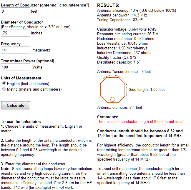
So, the specified conductor length is not ideal but the comments section says were under the 1/4 wavelength at 17 feet. What is also tells us is that, "For highest efficiency, the conductor length for a small transmitting loop antenna should be greater than 1/8 wavelength (greater than about 8.52 feet at the specified frequency of 14 MHz)." 

That is OK, we know that the MLA is going to be less efficient somewhere in its range and the suggestion of 8.52 feet is close enough to our 8 feet we can ignore it. The 42% efficiency is not the greatest but -3.6dB is about half an S-Unit down so I'll live with that.

Just for fun I changed the copper pipe back to 1/4 inch and the efficiency dropped to 20% (-7 dB) so I think I'll stick with 3/4 inch. It makes more of a difference at lower frequencies since more current is flowing through the loop!

In order to tune the loop between 14MHz and 29MHz we look at the Tuning Capacitance value in the last two calculations above. At 29 MHz the tuning capacitance required is 19 pF and at 14 MHz it is 83 pF. 
This is well within the capacitance range of a normal air variable capacitor and in fact a larger capacitor with a maximum capacitance of 160 pF would allow you to reach the 30M band with reduced efficiency. 

Its important however to look at the voltage across the capacitor in our last two examples. At 29 MHz we'll see a Capacitor voltage of 2,562 volts RMS and at 14MHz we'll see a Capacitor voltage of 3,664 volts RMS.

What does this mean? In order to know what kind of capacitor would be best we need to know the absolute maximum voltage it will have to withstand before it arcs between the closest conductors. If the voltage is high enough it will 'leak' between the plates of the capacitor by breaking down the air between them and directly passing an electric current ... we don't want this to happen.

The breakdown voltage of air is around 3000V per milimeter (39/1000 of an inch = 1 mm). The voltage above is shown as RMS (Useful for power calculations) but we need to know the peak value which is higher and determines the maximum voltage. The peak voltage = RMS x 1.414 or 3664 x 1.414 = 5181 V peak. 

A peak voltage of 5181V will require a minimum spacing of 1.7 mm (peak voltage / breakdown voltage per mm) between the closest conductors in the capacitor. That would rule out an old air spaced variable capacitor from a vacuum tube radio but you could still use a wide spaced variable capacitor from an antenna matching unit or transmitter. A vacuum variable capacitor would be great (watch the minimum capacitance) or a home-made capacitor would also be fine provided you checked the breakdown voltage of the insulating material.

What if all you have is a capacitor with insufficient plate spacing for that voltage? If you reduce the output power to 35W then the voltage across the capacitor will decrease to 2168 V RMS which is 3066 V peak( 2168 x 1.414) This voltage requires a 1 mm plate spacing which is easily achievable with surplus capacitors. At QRP power levels (5 W) the voltage falls to 1160 V peak and requires only 0.39 mm between the plates, suitable for practically any variable capacitor!

The value of 3000V / mm is only an approximation and if possible use a capacitor rated for a higher voltage than you expect to run to prevent damage to your radio. Modern rigs have great protections circuits but they shouldn't be relied on.

Next post I'll cover building the loop and coupling it to your transceiver. Hopefully you found this information useful and if there are mistakes or inaccuracies you'll drop me a line and set me right.

Monday, February 13, 2012

What is the AM-6155/GRT-21 ?

FAA AM-6154/GRT-21 Amplifier
From the website of N1RWY

The FAA used the AM-6154 and 6155 amplifiers in the early 1980's as ground-to-air AM transmitters. The 6154 was designed to cover 118-136 MHz and the 6155 to cover 225-400 MHz. Both models were set to 50 watts output, and amplified an AM exciter.

Both models were rack-mount, 7" high, 19" wide, and about 24" deep; they weigh about 75 pounds and have an internal AC power supply that can be used on 120/240 VAC. They are built so they have a slip-in RF drawer that contains the RF amplifier itself. The main chassis holds the power supplies and a small blower. No T/R switching is included. Because they are intended to be used with the exciter, the amplifier circuitry expects to get some DC control signals from the exciter which have to be simulated by some modifications.

The reason the amplifiers are so interesting to V/UHFers is because they are capable of outputting over 400 watts on 2, 222 or 432 MHz with only a few hours work and almost no extra parts. This is because they use the 8930 tube (or the Amperex equivalent, the DX-393), which is basically a 4CX250R with a 350-watt anode. 50 watts average power of AM is actually four times that power peak; or 200 watts; and these things were designed to do that all day, every day. That's why they used such a high-power tube for only 50 watts output power.

The RF drawer of either model can be modified for ANY of 2, 222 or 432; but as it comes from the factory, modifications HAVE to be made for any of the three bands. In general, the mods involve redesigning the RF grid circuit to be more efficient and to tune one of the ham bands. The plate circuit in either model can be used on any of the three bands, although use at 400 watts on 432 MHz places a big strain on the stock plate DC choke and plate blocking capacitor, which almost always have to be reworked for serious 432 MHz use. They have apparently proven able to withstand high power on 144 and 222 MHz without modification, although the mods do not hurt.

The power supply chassis is composed of three smaller drop-in chassis, an additional metering PC board, and a 400 Hz 120VAC blower which is powered by a DC-to-AC converter (one of the three drop-in chassis). The high-voltage power supply uses a very compact and lightweight transformer, a dual-section oil-filled filter capacitor, two screen voltage dropping resistors and a string of three zener diodes to regulate the screen voltage. Another drop-in chassis houses the filament transformer which also provides grid bias power and another winding to provide power to the DC-to-AC converter which drives the very small, compact 400 Hz blower (which is able to cool the large tube due to the high speed, 5500 RPM, of the blower).

A front-panel-mounted meter with 12-position switch is also wired to a PC board which contains circuitry that originally monitored the output power and antenna VSWR in addition to the blower current, filament voltage, grid, screen and plate voltage, and plate current. The RF drawer contains a directional coupler and low-pass filter which are almost always removed from the output of the amplifier (and sometimes rewired to the input side) because they don't handle 400+ watts very well.

So, where can you get one?    
Most of the amps are sold by Fair Radio in Lima Ohio. They advertise in QST. Sometimes they can be found at hamfests and there have been reports that a few have been picked up from government surplus sales. Fair Radio asks $235 for the AM-6154 and $285 for the 6155. (Based on early 1997 figures) Fair Radio has by far provided the lion's share of them, probably well over a couple thousand to US hams alone.

They are extremely popular among US V/UHFers and usually command a $300+ price tag, whether modified or not (because the shipping alone totals around $35 for UPS Ground!). Recent estimates by Harry Brown, W3IIT of the Packrats, are that there are OVER several hundred in the Philly area alone; and Ev Tupis, of the Rochester VHF Group, estimates ALMOST that many in northwestern NY state! They're great amps - not 8877's but the price is hard to beat.

[ Thanks to Steve, KO0U/1, and Harry, W3IIT, for the summary and history of these fine amplifiers. ]

Sunday, February 12, 2012

Heathkit's first amateur transmitter - Heathkit AT-1

The Heathkit AT-1 represents the commercial embodiment of the simple Master Oscillator Power Amplifier (MOPA) transmitter using a crystal controlled 6AG7 oscillator plus a 6L6 final output tube.

Although it was possible to design and build a simpler transmitter, the goals of output power and stability could become mutually exclusive when trying to operate with only one tube. For a novice class license holder of 1951 the Heathkit AT-1 represented a solid performing rig that would be relatively easy to construct and operate.

The Novice remained the primary entry license until the Morse code requirement was eliminated for Technician licenses in 1990. On HF it permitted code transmissions only, with a maximum power of 75 watts, (input to the transmitter's final amplifier stage) on limited segments of the 80, 40 and 15 meter bands.

For $29.50 and the loan of a few tools you could get some use out of that new novice license
The earlier MOPA circuit from the ARRL handbook of 1941 below shows a layout remarkably similar to the circuit of the AT-1 although it is designed for plug in coils rather than the band-switching arrangement of the later Heathkit transmitter.
MOPA transmitter using a 6L6 and an 807 as the power amplifier (ARRL Handbook 1941)
For a little added complexity MOPA transmitters generally offered better stability of frequency and keying waveform than single tube crystal controlled or self exited rigs. The straight forward design of the AT-1 should have looked familiar to novice class hams after studying the ARRL handbook or other radio publications.
Heathkit AT-1 Circuit diagram showing band-switching arrangement and link coupled output
Once the novice had upgraded his license the AT-1 could be expanded by the addition of the Heathkit VF-1 variable frequency oscillator to allow transmission on any frequency within the allowed band.
The Heathkit VF-1 Variable Frequency Oscillator
The VF-1 covered 160-80-40-20-15-11-10 meters and used an OA2 voltage regulator tube to provide a stable voltage for the oscillator. Ceramic coil forms, solid construction and high quality components were used to help increase stability.

It was recommended that to correctly couple an antenna to the AT-1 you would use an antenna coupler such as the Heathkit AC-1 which also included a low pass filter.

The Heathkit AC-1 Antenna Coupler. Designed to attach to a single wire by the insulated post on the front panel.
Heathkit AC-1 Antenna Coupler circuit diagram
Although Heathkit did not produce a AM modulator for the AC-1 there is provision for modulator connection on the rear panel. The earlier ARRL manuals have several suitable circuits for modulators that would work with the AC-1. Most functioned by driving a modulation transformer with the output from an audio power amplifier. The secondary of the modulation transformer would be carrying the DC plate supply for the power amplifier tube plus or minus the instantaneous voltage of the audio waveform. By changing the plate voltage to the final amplifier tube the radio frequency output would be controlled by the amplified audio frequency resulting in amplitude modulation.

Saturday, February 11, 2012

South Texas Balloon Launch Team launches balloon aimed at China

My daughter and I made the short trip to the No Label Brewing Company in Katy TX to watch the South Texas Balloon Launch Team launch a helium balloon aimed at Nanjing China. Thanks to Tom AE5QB for letting us know about this event!

To track the balloon in real time go to : http://aprs.fi/?call=a%2FKT5TK-11&_s=mb


From the press release of the South Texas Balloon Launch Team:

The South Texas Balloon Launch Team is pleased to announce the upcoming launch of its twenty-eighth, helium-filled, unmanned balloon in twenty one years. The purpose of this flight is to establish a world record for distance by floating a balloon from Katy, Texas to Nanjing, China.

The balloon will be released at approximately 3 P.M. CST on Saturday, February 11, 2012. The site of the launch is at the western end of the No Label Brewery complex at 5373 First St., Katy Texas, near the old rice grain silos.

The public is invited to this free event, with a special invitation to science students and teachers. Free helium-filled balloons will be available to the first 100 students. Sorry, no pets allowed in the balloon area.

The balloon payload package weighs only about five ounces (150 grams) and contains a high altitude GPS tracking system and a VHF amateur radio transmitter. To conserve weight and battery life, no camera equipment will be on board. The maximum altitude is expected to be above 100,000 feet, with horizontal speeds between 100 and 150 MPH. The balloon size will increase from about five feet to about 39 feet at maximum elevation. Recovery of the payload package is not expected.

Individuals may follow the balloon's progress on the Internet by logging onto APRS, filling in the "track callsign" field with "kt5tk-11", and change the "show last" to 24 hours.

The South Texas Balloon Launch Team is composed of about twenty active amateur radio "Ham" operators from a variety of occupations who donate their time and expertise.

We appreciate the continued support by No Label Brewing Company for our amateur radio projects.

Thursday, February 9, 2012

Now I understand - Standing Wave Ratio (SWR)

There are great books out there that explain radio principals in a plain and straightforward manner. Many are vintage military manuals whose primary aim was to give a functional understanding of the theory involved without getting caught up in the interesting but ultimately unnecessary details.

Modern material on the other hand can sometimes miss the mark of providing a functional understanding in favor of trying to completely address the high level theory and leaving practical matters to be addressed later ... or perhaps never.

The AT&T training video certainly hits the mark when it comes to explaining and showing the properties of radio waves. It shows how they are affected by termination and changes in impedance, what resonance looks like, how terminated and non-terminated lines reflect waves and much more.

Material like this is well worth the time of anyone who has an interest in radio or electronics.


More video are available from the AT&T archives here : http://techchannel.att.com/showpage.cfm?ATT-Archives

Wednesday, February 8, 2012

Virtual Tour of W1AW, the Hiram Percy Maxim Memorial Station

Virtual W1AW Tour on Sunday, February 12 at 5 PM EST (2200 UTC)

Join W1AW Station Manager Joe Carcia, NJ1Q, on a virtual tour of W1AW, the Hiram Percy Maxim Memorial Station, the Amateur Radio station at ARRL Headquarters in Newington, Connecticut. Carcia will lead this tour via a live webcast on . Anyone with an Internet connection will be able to watch the tour here.

W1AW - The Hiram Percy Maxim Memorial Station

"We want viewers of this live Internet tour to feel as if they are actually at W1AW," Carcia explained. "If you came to W1AW in person, you would see the same things that we are going to show on the virtual tour: The three operating stations, the W1AW workshop, the transmitter racks that we use to send out our bulletins and use for the code practice transmission, the control console and Old Betsy, Hiram Percy Maxim's personal spark gap transmitter."

Al Petrunti, KA1TCH, of the New Day Group, will follow Carcia as he leads viewers through the station. ARRL Staff members, including Media and Public Relations Manager Allen Pitts, W1AGP, and Chief Operating Officer Harold Kramer, WJ1B, as well as local television weatherman Geoff Fox, K1GF, will also be on hand at W1AW during the tour.

"Hams around the world know of W1AW, and thousands have made contacts with this impressive station -- but most hams never get to see it," Pitts said. "Thanks to Al Petrunti's group, we hope that folks enjoy seeing what's at the other end of the signals. As in all live broadcasts, you never know just what might happen. We invite you to join us." Pitts is producing the live web tour.


From the ARRL Letter, available at http://www.arrl.org/arrlletter?issue=2012-02-09

Tuesday, February 7, 2012

The KN-Q7A - A new 40M SSB 10W transceiver kit

Amateur radio kit builders have had greater opportunities to construct high-end equipment thanks, in part, to more economical production processes. Online services allow kit manufacturers to farm out circuit board production to large workshops where jobs are batched together into larger production runs with significant cost savings. A number of suppliers are now willing to sell in smaller amounts while maintaining low costs due to automated on-line processing. The end result has been an increase in the number of kits available of significant complexity including rigs with using sideband, digital signal processing and software defined radio.

One new SSB rig kit is the KN-Q7A available from Adam Rong BD6CR/4, designed by Shi Ke BA6BF. The KN-Q7A is a 40M SSB transceiver in a compact case with VXO tuning and 10W power out. This style of rig would be ideal for back-packing, camping or as a compact emergency transceiver.

It would be interesting to see how this would pair with the NUE-PSK Digital Modem for a ultra-compact portable PSK31 station if the VXO could be made to tune to 7.035 MHz

The KN-Q7A - 40M with VXO SSB 10W
The KN-Q7A is available directly from http://crkits.com/ or from their US distributor http://www.qrvtronics.com/HAM-Radio

Price for the KN-Q7A kit is $125 USD, a suitable microphone is available for an additional $25 USD.

Specifications

• Dimension: 153 mm x 97 mm x 40 mm, not including protruding features
• Weight: 500 g or 1.1 lbs
• Power Supply: 12~13.8 V, 3 A
• Current consumption: 30 mA in RX and about 2 A in TX @ 13.8 V
• RF output: about 10 W PEP @ 13.8 V
• Spur suppression: better than -43 dBc
• Sensitivity: better than 0.5 μV at 10 dB SNR
• IF filter: 6 pole crystal ladder filter + 1 pole post IF amplifier crystal filter
• IF bandwidth: about 2.0 kHz
• IF frequency: 8.467 MHz or 8.192 MHz, depending on the selected tuning range
• Frequency tuning range: about 20 kHz in VXO type. Five options: 7.050~7.070 MHz,
7.080~7.100 MHz, 7.145~7.165 MHz, 7.200~7.220 MHz, or 7.280~7.300 MHz
• Connectors:
• Speaker output: 3.5 mm connector, mono output
• Microphone input: 8-pin, can be configured to be compatible with electret
microphones
• Antenna connector: SL-16 type (M or SO-239 type equivalent), rear panel mount
• Controls:
• IF Gain Control: act as volume control
• Tune Control
• On board RF Attenuator trimmer to eliminate broadcast interference