Monday, March 5, 2012

DIY Magnetic Loop Antenna - Part 3

Well, I finally have had time to sit down and put together part three of the DIY Magnetic Loop Antenna, sorry it has taken so long!

This post will cover building and coupling the loop to your transceiver. After reading through posts one and two you should have a good idea of the parts you'll use and the physical dimensions of the main loop.

DIY Magnetic Loop Antenna - Part 1
DIY Magnetic Loop Antenna - Part 2

Most magnetic loops have the capacitor at the top of the main loop and the gamma match or matching loop at the bottom, this arrangement avoids running the feed-line through the center of the antenna.

You can assemble the main loop from continuous copper tube or from eight straight sections and 45 degree joiners. Make sure you have a blow torch or propane torch to solder the joints as you'll need more heat than a soldering iron can supply. Whichever way you decide to build the main loop make sure that all joints are soldered or clamped as securely as possible, you want the lowest resistance possible to avoid your output power turning into heat. Other materials can be used for the main loop such as aluminium or low loss coax but copper pipe is easy to work, has low resistivity and available from just about every hardware store.

To construct the frame of the antenna you can use PVC pipe. It is a cheap and relatively sturdy building material and is available in a range of thicknesses, just about any hardware store will stock a wide selection of fittings. It insulates well and can be glued once you are sure your project is in its final form.

Once the main loop is constructed you'll need to connect your capacitor to the two ends of the pipe at the top of the loop. Depending on the capacitor you may want to solder tags to the ends of the loop so they will be easier to attach. Copper pipe is a great conductor of heat and takes a lot to heat up and solder while it is not advisable to apply the same amount of heat to your capacitor.
It is also a good idea to attach the capacitor to a solid support so that the connections are not under strain.
The main loop and the capacitor forms the resonant circuit of the magnetic loop antenna.


To couple the main loop to your transceiver and match the expected 50 Ohms impedance you can use one of two methods. Probably the easiest is to use is a loop of insulated wire 1/5 the circumference of the main loop. The smaller loop is placed at the bottom of the main loop and can be shifted around to provide the best match. If you have an antenna analyzer you'll be able to set it to the desired frequency, tune the variable capacitor for resonance and then move the small matching loop around till you have achieved close to 1:1 SWR. If you don't have an antenna analyzer you can tune the capacitor for the greatest received noise and then on low power tweak the capacitor and move the coupling loop around for best SWR. Do NOT touch the loop while it is transmitting, use a wood or plastic rod to make adjustments as there are high voltages and intense RF fields near the loop.
An alternative to the coupling loop is the gamma match. The shield of the coax feed cable is connected to the base of the main loop while the inner conductor is connected to a point approximately 1/5 of the circumference around the loop. Its a good idea to use stiff wire (large gauge) for the gamma match as it can be critical of the position and orientation and once you have it in the right position you won't want to move it again.
It would be preferable to have the ability to remotely tune the loop. A motor with a reduction gear could be used to move the variable capacitor but because the point of resonance is very narrow there should be a way of slowing the motor down. A simple control circuit using variable pulse width modulation could be used to slow the motor down while still retaining enough torque to move the capacitor. Whatever method is used to move the capacitor it should be well insulated from the other components of the antenna. Several thousand volts are generated on the MLA and care should be taken to ensure they don't find their way onto control leads and back into the shack. Control leads should also be wrapped around toriod inductors as they leave the near field of the antenna to reduce the possibility of RF travelling along them.

With a SWR bridge and microcontroller you could build a fully automatic tuner that swept through the range of the tuning capacitor when the SWR rose above a defined limit indicating that the transmit frequency had changed.

With a little creativity and knowledge you could have an impressive MLA the equal of multi-thousand dollar military style units.

Hopefully this has given you some ideas for constructing your own loop antenna. Regardless of if you go top-of-the-line and buy a vacuum variable or build for economy and QRP you'll have a compact, useful and unique antenna.

Tuesday, February 28, 2012

What has been happening?

Anyone looking at my blog could be forgiven for thinking that I had dropped off the face of the earth for a while, has nothing been happening in my world?

Well, the answer is that a LOT has been happening and all at once. My daytime job has become busier and there have been several non-radio projects at home that needed to be completed. All this has kept me away from Amateur Radio blogging even though I have spent more time on the computer than usual.

In between projects I did manage to stumble across this video of Rear Admiral Grace Hopper explaining just how "long" a nano-second is and what it looks like. This has relevance to radio as we're usually well aware of frequency and wavelength but don't usually spend too long thinking about speed.


From Wikipedia : Rear Admiral Grace Murray Hopper (December 9, 1906 – January 1, 1992) was an American computer scientist and United States Navy officer. A pioneer in the field, she was one of the first programmers of the Harvard Mark I computer, and developed the first compiler for a computer programming language. She conceptualized the idea of machine-independent programming languages, which led to the development of COBOL, one of the first modern programming languages. She is credited with popularizing the term "debugging" for fixing computer glitches (motivated by an actual moth removed from the computer). Because of the breadth of her accomplishments and her naval rank, she is sometimes referred to as "Amazing Grace." The U.S. Navy destroyer USS Hopper (DDG-70) was named for her, as was the Cray XE6 "Hopper" supercomputer at NERSC.

Thursday, February 23, 2012

Morsemail and LCWO.net

The time has come when I can't put off learning Morse code any longer, With an interest in vintage amateur radio and the impending restoration of a Heathkit AT-1 I'm going to need to use CW sooner or later.


So I have been checking out resources for learning Morse code and stumbled across two that really intrigue me.

The first is LCWO.net, a web browser based Morse code learning tool that is usable on any internet connected computer. It is available free of charge and there is no software to install. LCWO.net keeps track of where you are in your lessons and where you need to concentrate your effort. The Koch method is the primary tool available but they also offer code group practice, callsign and plain text training modes along with a service to convert text to Morse MP3s for download and use offline.

Once you are on the way to CW proficiency and want to communicate with others you can always fire up a rig and get on the air ... What if you don't have a rig or need a confidence boost before 'going live'?

Well, you could always send Morsemail using the Morsemail client from http://brasspounder.com:8873/.

Morsemail is, "A simple text format that encodes mark and space times to make it possible to send Morse coded messages via email" but a recently added feature allows for QSOs using a internet repeater hosted on brasspounder.com. You can use a mouse or actual key wired to the mouse or joystick buttons to send CW which can be emailed or sent through the repeater live.

Now I just have to carve out the time to sit down and use these resources!

Tuesday, February 21, 2012

DIY Magnetic Loop Antenna - Part 2

Part 1 of the DIY Magnetic Loop Antenna covered mostly theory and materials so now its time to move on to designing the magnetic loop antenna (MLA).

If you have priced a commercially made MLA you'll see prices start at $400 and keep going up, and up. If they cost so much you would think they must be difficult to build or use expensive parts, right? Well, it is certainly possible to spend more and get a higher quality MLA but a low cost MLA will still work very well.

For the purposes of this article we'll assume that you want to build a loop to cover the 20-10M bands. I'll run through the calculations required to build the MLA.

The required information for the MLA calculator is:
  1. Length of the loop
  2. The conductor diameter
  3. Frequency/s of operation
  4. Input power to the antenna
Lets pick some starting values
  1. We don't really know the best length of the loop at the moment so I'll pick 9 feet circumference as a starting point (It'll still fit in the trunk of my car)
  2. Since we seem to be having better luck with sunspots now I'd like to try 10M so we'll start with 29 Mhz as the highest frequency we'll use.
  3. I have some copper pipe left over from an ice-maker install, it is 1/4 (0.25) inch in diameter.
  4. Input power to the loop will be 100W.
Using the 66pacific.com calculator we get the following:
The comments section informs us that, "The specified conductor length is not idea" and we can go on to read that, "To avoid self-resonance, the conductor length for a small transmitting loop antenna should be less than 1/4 wavelength (less than about 8.23 feet at the specified frequency of 29 MHz)."

Well, I don't want the wire in the loop to resonate by itself, its designed to resonate in combination with the capacitor. Lets make the loop 8 feet in circumference and while I'm at it I'll make it out of 3/4 (0.75) inch copper pipe for better conductivity.

Lets see what we have now:
Well, that seems to have fixed the self resonance issue and we've managed to bump up the antenna efficiency to 91% from 82% ... not a huge increase ( About 0.5 dB) so I could use either diameter copper tube in this case. Everything looks good so far!

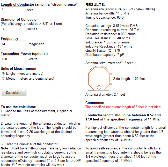
How about the 20M band, at 14 MHz how do things look?
So, the specified conductor length is not ideal but the comments section says were under the 1/4 wavelength at 17 feet. What is also tells us is that, "For highest efficiency, the conductor length for a small transmitting loop antenna should be greater than 1/8 wavelength (greater than about 8.52 feet at the specified frequency of 14 MHz)." 

That is OK, we know that the MLA is going to be less efficient somewhere in its range and the suggestion of 8.52 feet is close enough to our 8 feet we can ignore it. The 42% efficiency is not the greatest but -3.6dB is about half an S-Unit down so I'll live with that.

Just for fun I changed the copper pipe back to 1/4 inch and the efficiency dropped to 20% (-7 dB) so I think I'll stick with 3/4 inch. It makes more of a difference at lower frequencies since more current is flowing through the loop!

In order to tune the loop between 14MHz and 29MHz we look at the Tuning Capacitance value in the last two calculations above. At 29 MHz the tuning capacitance required is 19 pF and at 14 MHz it is 83 pF. 
This is well within the capacitance range of a normal air variable capacitor and in fact a larger capacitor with a maximum capacitance of 160 pF would allow you to reach the 30M band with reduced efficiency. 

Its important however to look at the voltage across the capacitor in our last two examples. At 29 MHz we'll see a Capacitor voltage of 2,562 volts RMS and at 14MHz we'll see a Capacitor voltage of 3,664 volts RMS.

What does this mean? In order to know what kind of capacitor would be best we need to know the absolute maximum voltage it will have to withstand before it arcs between the closest conductors. If the voltage is high enough it will 'leak' between the plates of the capacitor by breaking down the air between them and directly passing an electric current ... we don't want this to happen.

The breakdown voltage of air is around 3000V per milimeter (39/1000 of an inch = 1 mm). The voltage above is shown as RMS (Useful for power calculations) but we need to know the peak value which is higher and determines the maximum voltage. The peak voltage = RMS x 1.414 or 3664 x 1.414 = 5181 V peak. 

A peak voltage of 5181V will require a minimum spacing of 1.7 mm (peak voltage / breakdown voltage per mm) between the closest conductors in the capacitor. That would rule out an old air spaced variable capacitor from a vacuum tube radio but you could still use a wide spaced variable capacitor from an antenna matching unit or transmitter. A vacuum variable capacitor would be great (watch the minimum capacitance) or a home-made capacitor would also be fine provided you checked the breakdown voltage of the insulating material.

What if all you have is a capacitor with insufficient plate spacing for that voltage? If you reduce the output power to 35W then the voltage across the capacitor will decrease to 2168 V RMS which is 3066 V peak( 2168 x 1.414) This voltage requires a 1 mm plate spacing which is easily achievable with surplus capacitors. At QRP power levels (5 W) the voltage falls to 1160 V peak and requires only 0.39 mm between the plates, suitable for practically any variable capacitor!

The value of 3000V / mm is only an approximation and if possible use a capacitor rated for a higher voltage than you expect to run to prevent damage to your radio. Modern rigs have great protections circuits but they shouldn't be relied on.

Next post I'll cover building the loop and coupling it to your transceiver. Hopefully you found this information useful and if there are mistakes or inaccuracies you'll drop me a line and set me right.

Friday, February 17, 2012

DIY Magnetic Loop Antenna - Part 1

Do you live in a neighborhood with a restrictive antenna policy and despair of having a useful HF antenna?

Can you solder or know someone who can?

A magnetic loop antenna may be the answer and they are not as difficult to build as you might think. Like getting on the air for the first time or taking your license exam there is a certain amount of uncertainty when you first approach magnetic loop antennas, there are a few new ideas to grasp. However, thanks to other hams like Steve AA5TB there are tried and tested designs, calculators & building methods that are known to work and that you can follow.

At the heart of every radio and MLA (Magnetic Loop Antenna) is the resonant circuit. The combination of an inductor (a wire has inductance, but a coil of wire has more) and a capacitor (two conductors separated by an insulator) in a circuit will resonate or 'ring' at a certain frequency. Sound vibrations at a certain frequency can cause a piano string to vibrate in sympathy and a vibration of the correct radio frequency will cause a resonant circuit to electrically vibrate in sympathy.
Since there is no such thing as a free lunch, the sacrifice you make with a MLA is that it needs to be re-tuned whenever you change frequency on your transceiver. The frequency range over which it is resonant is very small, typically only a few hundred kilohertz at the most.

The materials you can get your hands on is going to decide the capabilities of your MLA. Ideally you'll have a loop made from a conductor with very low resistance (usually copper) and a capacitor that can handle high voltages. A variable capacitor is required if you want to use your antenna on multiple frequencies but you can use or make a fixed capacitor if you operate on one frequency, for Eg PSK31.


A MLA calculator like the Excel spreadsheet from Steve AA5TB or this web page from 66pacific.com will help you to decide what size components you'll need to make your antenna.

The four pieces of information required are:

  1. What frequency or frequencies do you wish to transmit on?
  2. How large do you want the loop to be (It should have a circumference less than 10% of the design frequency wavelength, both calculators help you figure this out)
  3. The diameter of your conductor (Three quarter inch (0.75 inch) copper pipe is a good start)
  4. How much power you want to use (The voltage across the capacitor is proportional to the input power to the MLA)
A MLA of a certain circumference will be more or less efficient based on the frequency you transmit at. It is worth changing the loop size in the calculator to get the best efficiency possible in your favorite band. 
For example, my 30-10 Meter loop is 8.5 ft in circumference and 23% efficient at 10.1Mhz but 91% efficient at 28Mhz. This represents a difference of about 6dB or 1 S-Unit.

The diameter of the conductor determines its resistance and this becomes important due to the large current flowing through the loop. Large diameter copper pipe is better since the radio frequency current flows primarily on the outside of the conductor rather than the core. Typical 3/4 inch plumbing pipe is a good balance between low resistance and weight, Heliax coax is good for portable antennas where the loop has to be rolled up into a compact space.

Probably the most problematic part of the MLA is the tuning capacitor. While everything else can be found in your junk box or on a shelf at the local hardware store the capacitor takes a little more digging. Ideally it should be variable from a minimum to a fairly high capacitance (0-300 pF would be good) it should also be able to withstand high voltages. If you are planning to run 100W then you could expect at least 4000 volts across the capacitor. This is not as bad as it sounds as it takes 3300 volts to jump just 1mm or .04 of an inch.

Ideally you could purchase a vacuum variable capacitor, the Rolls Royce of high voltage variable capacitors. You would expect to pay anywhere from $100 up when buying a 10 - 500 pF unit on Ebay and a LOT more if you buy new. If that is the way you want to go then great, you're all set. If not then read on ...

There are several alternatives to the vacuum variable capacitor that will work almost as well. The primary concern now becomes resistance and plate separation. For QRP power levels you can use the tuning capacitors from old vacuum tube radios, the type that have a set of fixed metal plates and a set of moving plates that mesh into them.
For higher power there are two other types of capacitor that are suitable. 
One is the split-stator capacitor, so called because each terminal of the capacitor is connected to a stator that is electrically isolated from the other and the frame. The rotors and shaft form the rest of the circuit so there is very low resistive loss and no sliding contacts.
The other type is called a butterfly capacitor due to the shape of the rotor plates. In this type the stator plates are placed opposite each other with the butterfly rotor in between. When each of the butterfly "wings" are fully meshed between the stator plates the capacitor is providing maximum capacitance, when rotated 90 degrees the wings are completely un-meshed and the capacitor is providing minimum capacitance. Because of the construction of butterfly capacitor there is a higher minimum capacitance that should be noted when planning the frequencies your loop will cover.
If all else fails then you can construct your own variable capacitor. The idea is to have two conductors separated by an insulator, the larger the area of the conductors and the better the insulator the higher the capacitance. Sliding metal plates, trombones of copper tube and even Coke cans have been used as variable capacitors.

A fixed capacitor can be created out of coaxial cable if you intend to operate on one frequency and a table of approximate capacitances for different types of coax is included here, click to enlarge the table below.

You can cut a length of coax a bit longer than the length suggested by the table above and trim it to frequency once it is attached to the loop. Make sure there are no stray pieces of braid between the shield and the center conductor as the voltage rating is determined by the spacing of the two closest conductors.

Part two of this post will continue with calculating the antenna dimensions and performance.

One important thing to remember ... If you don't have access to the best materials then use what you have and improvise. If you don't have copper pipe then use coax or heavy wire. If you don't have a high end variable capacitor then use what you can find and keep the power levels QRP. The only antenna that is a complete failure is the antenna you never get around to building.