Showing posts with label high voltage. Show all posts

Friday, July 18, 2014

Richardson "5" - 1925

I recently purchased a Richardson "5" TRF receiver and after bringing it home discovered somewhat disappointingly that, although in excellent condition appearance-wise, this radio is not going to play without a significant amount of work.

Although it was sold to me with the opinion that it did play, I think it more likely that it played at some point in the past ... although I'm willing to give the seller the benefit of the doubt.

The Richardson Radio Inc of New York seems to have appeared on the scene in 1925, lasting perhaps a year and then vanishing. The Richardson "5" features neutralization but doesn't appear to mention licencing that technology from Hazeltine so this may have had something to do with their short life.

The chief problem seems to be the wiring which is soldered in only a few places and otherwise consists of stakes or posts that have been pushed through the insulation of the wires in the same way that inexpensive garden lights are sometimes put together.

Given time, almost 90 years in this case, the poor contacts and gradually deteriorating insulation have done a good job in turning almost every connection into an intermittent connection. When I powered the radio up it was obvious that the two stages of audio amplification were working but touching any wire in the RF amplifier or detector sections just changed the quality of the noise in the headphones. I was never able to tune in a station or even see if the RF sections were working.

So, I have a choice. This radio can either be dust collector on the shelf and an example of how not to wire a set or I could re-wire it using proper soldered connectors which wouldn't be "authentic".

Not sure what to do exactly. Not that I will be diving into it any time soon, I still have the AK20 restoration to complete before I start anything else.

It didn't come with a speaker but I didn't find any evidence that Richardson Radio ever sold a loud speaker and the example at the top of the page uses a "Superspeaker Console" from the Jewett Radio & Phonograph Co.

The Richardson "5" uses a six volt "A" battery and "B" battery voltages of forty five and ninety volts. When running from the ARBE III supply I set the "A" battery voltage to five volts so there is little risk of burning the five 01A tubes too brightly.

All-in-all I would say that it is a handsome set that will look good on the shelf and may eventually be made to work again. It will be interesting to see what difference the neutralization makes to a circuit that is essentially identical to the AK20.

Friday, June 27, 2014

Atwater Kent Model 20 "Big Box" - 1924

Ok, you got me. This isn't technically an amateur radio blog post but I would argue that radio in the early 1920's was the pursuit of the amateur, the enthusiast and the tinkerer. The amount of crossover between commercial broadcast radio and amateur radio in those days was much greater than it is now. Anyway, that's my excuse ... but why the Atwater Kent Model 20?

The model 20 or AK20
Well, to make along story short, I found an example of this Atwater Kent model sitting in a flea market stall in Hot Spings Arkansas. It looked like it had seen better days but was fully complete including the five '01A' vacuum tubes. The owner wanted $200 for the radio and explained the better part was the included horn type loud speaker which was worth $150. The horn speaker looked to be in fairly bad shape and lacking any way to test it I cheekily asked if he would take $50 for the radio ... "Sure", he said and my wallet was instantly $50 lighter.

Now I have a few vintage radios at home, perhaps a few too many depending on who you ask, and I consider them all to be interesting examples in their own right. More or less money, time and research was employed to create these radios and a great variety of circuits and designs was the result.

First impressions told me this was different, I had never owned anything like the Atwater Kent radio before. It was certainly older than my other radios but it was also constructed unlike any other radio I owned. Even under layers of grime, dust and mud dauber's nests this was obviously an article of quality. The finish on the wood cabinet and the metal front panel had seen some heat and were very badly checked in addition to the 90 or so years that had taken its toll. On the lip of the hinged top was a protected area which still showed how the finish looked originally, the dark mahogany and subtle gloss hinting that it had once looked very smart indeed.

The model 20 compact or AK20C
Once I had Internet access again I started to research the model 20 and try and learn something about it. It was at this stage, after some initial confusion, that I noticed that my model 20 was the older and perhaps slightly rarer "Big Box" version. There isn't much between them but some important differences crop up as far as restoration goes, for example:

Most references I found online suggested that the front panel of the model 20 was painted with a crinkle finish however this was only true of the later versions.

In an Atwater Kent advertising booklet, published at the time, they write, "The front of the cabinet is of metal with a deep brown mat surface which brings out the sparkling sheen of the lighter brown Bakelite dials, knobs, etc., and the nickel-plated trimmings."

I'll need to clean my Bakelite parts and possibly wax them to bring up the original "sparkling sheen" of the tuning, aerial tap and filament rheostat knobs.

A suggestion from the Antique Radio Forums that Rust-Oleum Earth Brown paint followed by black KIWI boot polish applied using 0000 steel wool sounds like it would come pretty close to producing the right finish and will probably be the path I choose when I refinish the front panel.

This AK20, from The Backwood Realm, appears
to have the original finish and looks similar to mine.
For the woodwork we're fortunate to find the description below and some more research indicates that nitro-cellulose lacquer was used at the time and is still available now.

"The cabinet of the Model 20 Receiver, pictured above, is of solid mahogany, stained a dark brown, then shellacked, triply lacquered, and rubbed to a dull, glossy, long-wearing finish."

Overall it seems very understated compared to modern electronics, even down to "The name plate, of dull bronze, is both distinctive and unobtrusive."

I hardly need to say, to most folks at least, that Ebay is a wonderful, and terrible, place to shop for antique radio parts. Wonderful because at any one time there are parts available for just about any radio you might have and terrible because you'll be jostling with tens, or hundred, or thousands of other collectors and re-sellers ... many of which have some very deep pockets indeed!

Unused Atwater Kent Radio Log card.
After vowing I would never pay Ebay prices I lasted approximately 3 minutes and then started looking on Ebay for some of the things I knew I was missing.

Before too long I had found an all-important unused "Atwater Kent Radio Log" card and envelope. I intend to scan these items in with a high resolution flat bed scanner and make copies to use and share.

Also I was able to get a set of three tuning knobs since one of the originals on my radio was shattered. Although someone had thoughtfully placed the remains inside the cabinet it was never going to piece back together well enough to look "right"

I had found the Atwater Kent Radio Instruction Book Vol. 2 online and printed out a copy but couldn't resist the temptation to pick up an original as well as another envelope along with some instruction sheets for various models of AK loud speakers.

I already own a modern ARBE-III battery eliminator so this really left only one thing to find ... a loud speaker.

Even the parts you don't see, are expensive.
I should have known that finding "the right loud speaker" for the model 20 would not be a simple task. While it will work with many different speakers including later cone style Atwater Kent units and those manufactured by other companies, the "right" speaker ... the type shown in all the period advertising literature ... is the Atwater Kent type M, L, H or R radio speaker.

All but one of those models allegedly used pot metal in their construction which eventually succumbs to the dreaded "pot metal disease" making it crack and expand. I have dealt with pot metal disease before and have no intention of doing battle with it again ... this left one model, the model M, as the one I was looking for.

Ok, so there was one model M listed on Ebay and it looked to be in good condition as well as "working" according to the seller. In fact the more I looked at it, the better it looked ... it seemed to be in very nearly new condition. After I finished drooling over the photographs I decided that I would limit myself to $100 not including the $50 shipping involved. The shipping was more than average and I hoped this would keep bids low and reduce the amount of interest. This seemed to work for a while ... the bids topped out at around $80 and I thought I might be on a winner, however this was short lived and the bids jumped to over $100 and kept on going. "Ah well", I thought, "such is life". I knew there would be an vintage and antique radio auction coming up in a month and I could probably find something there at a reasonable price.

The Atwater Kent Type M Loud Speaker.
At this point I took a shower, which is something I would recommend to anyone suffering some disappointment ... or a bath. Worst case you end up cleaner if still disappointed which is surely a small improvement.

At the same time my wife, who perpetually despairs of ever buying the right gift for a husband who is notoriously difficult to buy for, noticed my dejection and moved over to my computer which I had foolishly left logged into Ebay (I should know better, really).

A furious round of bidding started between my wife and a number of others who knew little of her determination to win this auction. I won't mention the final amount, I would like to say because, "One doesn't discuss money" but mainly because it still makes me a little woozy to think about.

If you were bidding on that same speaker then I apologize, but you never really stood a chance.

After further research I've learnt a bit more about the internals of the AK20 and uncovered the meaning behind its three tuning dials and various other controls. In order to provide more amplification, not to mention more selectivity, the AK20 uses three largely identical tuned circuits. Each tuned circuit is controlled by a separate knob on the front panel and all three must be "in agreement" before you will hear anything from the loudspeaker. Next comes the detector circuit which converts the amplitude modulated radio frequencies into audio frequencies and finally two further stages of audio amplification.

The other controls on the front panel are the aerial tuning switch which selects different taps on the first set of coils and the filament rheostats. The filament rheostats, in addition to correcting the voltage supplied by the batteries to the vacuum tube filaments, also act as the volume control by lowering the filament voltage which in turn lowers the volume from its maximum to a comfortable listening level.

Next steps will involve re-finishing the front panel and cabinet, checking tubes along with the few capacitors and resistors, then a careful power-up with high impedance headphones ... the AK loud speaker can wait until I am absolutely sure that it is working as intended!

I hope to update the blog as I progress, as well as uploading pictures and more detailed data such as circuit diagrams and service information HERE.

Friday, November 8, 2013

Shock and Awe - The story of electricity.

Amateur radio has a long history, going all the way back to wireless experiments in the late 1800s. However the study of electricity has its roots in the observation of natural phenomena and stretches back much further.

I ran across this excellent three part documentary detailing the story of the discovery of electricity. The presenter is Jim Al-Khalili, currently Professor of Theoretical Physics and Chair in the Public Engagement in Science at the University of Surrey. He not only knows his stuff, he is also an interesting and engaging speaker.

The documentary runs for three hours but is worth your time if you are interested in the story of electricity and the people behind its discovery and history. I hope you find it as enjoyable as I did.

Sunday, May 13, 2012

Hollow state decade counter.

If you have looked through my blog you'll know that I have a soft spot for tubes and tube technology. At a time when our understanding of electron mechanics and quantum theory was still in development the manufacture of advanced vacuum tubes was part science, part physics and part art.
Special purpose tubes were developed in their thousands to meet the needs of commercial, scientific and industrial applications. Their form and functions were as varied as the devices they were installed in. Sometimes tubes were developed to meet a specific need and sometimes new tubes were developed for applications not yet in existence.
The E1T tube is impressive even among special purpose tubes. It functions as a decade counter with an inbuilt display! Many years later it would take several chips and associated display circuitry to achieve the same result using solid state components.
This is a somewhat long introduction to the excellent article by Ronald Dekker on the people and the story surrounding the development of vacuum tubes technology in Holland and the E1T tube in particular.
If you have a moment take a look at The making of the E1T by Ronald Dekker and revisit a time when electronics, physics and art were brought together to create 'technology for a better tomorrow".

Sunday, March 11, 2012

PC power supplies for Amateur Radio equipment?

I've noticed a few spirited discussions regarding modifying computer power supplies for use with Amateur Radio equipment. On the surface it seems as though they supply the perfect solution: Inexpensive, high current, regulated 12V DC supplies for a fraction of the cost of specialized amateur equipment. Is it really is as straight forward as lopping off a molex connector and replacing it with an Anderson Powerpole?

By design PC power supplies are designed to output a fairly well regulated 3.3V & 5V to the PC motherboard and 12V to the motherboard, fans and hard-drive motors. Modern units are typically rated anywhere from 75W to 1200W which should be a measurement of the output power available from all the 3.3, 5 and 12 volts. Since this isn't a lab grade power supply you can expect marketing hyperbole has perhaps inflated the power output figures.

Back when my job was to build PCs I had an issue with a server not being able to start its complete complement of disk drives. When I opened the case I found a 300W desktop supply board had been used in place of the 800W board ... sometimes you don't even get what you pay for!

Before you convert your first PC power supply there are two issues that may, or may not, cause a problem depending on your unit.

The first is load regulation or the ability of the power supply to maintain its rated voltage under load. If the output voltage drops too far your rig will shutdown, distort or fail to provide its rated output power.

The second issue is due to the high frequency switching circuits used in switch mode supplies. Depending on the individual power supply there can be adequate to no filtering to prevent radio frequency interference being broadcast to your receiver. Toroids on the input and output lines can help to reduce interference.

Because of construction differences between models and even between batch numbers for the same model you can never be certain how the power supply you purchase, or recycle, will perform. For the most part people's experiences have been positive but I have heard of power supplies that were unusable because of RF interference or such poor load regulation that the 12V rail dropped to 11V under load.

Without a motherboard presenting a load and supplying the power-on signal there are a few changes that need to be made to the power supply. Modern power supplies will not enable the 12V output unless the power-on wire is grounded and a load should be placed on the 5V line to help with regulation. Additionally there is usually an adjustment that can be used to raise the voltage above 12V

The following links detail the steps required to convert a PC supply for use with amateur radio equipment. Whether this represents a good investment of your time will depend on your desire to do-it-yourself and the quality of the power supply you begin with. I've heard strong opinions either way but I'll just say that, if luck favors you, you'll save some money and learn a few new skills in this exercise.

Computer Power Supply Converted for Ham Use

CONVERTING COMPUTER POWER SUPPLIES (Advanced with theory)

Converting Computer Power Supplies to stabilized 13.8 V DC 20 A

Tuesday, March 6, 2012

EICO Model 625 Tube Tester

I attended the Greater Houston Hamfest and as I walked past the tables of equipment I wondered if interest in vacuum tube equipment was starting to wane. Compared to the last few years the prices of collector quality gear had held steady but parts and restorable gear seemed to be going for less.  I'd like to know your thoughts if you've noticed trends one way or the other.

I was happy to pick up a EICO Model 625 tube tester for $15. It is in good condition and appears to work well. The roll of settings for each tube is in good condition and a little searching on the internet supplied settings for older tubes like the number 78 in the picture below.

EICO Model 625 Tube Tester with a number 78 tube
The EICO 625 is not a top of the line tester but it does basic tests and will let you know if a tube is functioning and an idea of the life left in it. It was sold in kit form for $34.95 in 1958 which is roughly equivalent to $274 in 2012.

Inside the EICO 625 from diyaudioprojects.com
The EICO 625 is fairly unique in having its own 6H6 diode tube to rectify the 30V filament voltage. It provides DC for the neon short-indicator bulb. If the tube is suspected of having a short then there is a fairly comprehensive series of tests than can be administered to isolate shorted elements.

EICO Model 625 circuit diagram
Here is the Users Manual and Roll Chart for the EICO Model 625 Tube Tester

Here is the complete TUBE TEST DATA 1/1/78 for the EICO Model 625 Tube Tester

Some settings for less common and older tubes are contained in : eico_625.zip

Excellent information on servicing and calibrating your Classic emission tube tester.

Monday, March 5, 2012

DIY Magnetic Loop Antenna - Part 3

Well, I finally have had time to sit down and put together part three of the DIY Magnetic Loop Antenna, sorry it has taken so long!

This post will cover building and coupling the loop to your transceiver. After reading through posts one and two you should have a good idea of the parts you'll use and the physical dimensions of the main loop.

DIY Magnetic Loop Antenna - Part 1
DIY Magnetic Loop Antenna - Part 2

Most magnetic loops have the capacitor at the top of the main loop and the gamma match or matching loop at the bottom, this arrangement avoids running the feed-line through the center of the antenna.

You can assemble the main loop from continuous copper tube or from eight straight sections and 45 degree joiners. Make sure you have a blow torch or propane torch to solder the joints as you'll need more heat than a soldering iron can supply. Whichever way you decide to build the main loop make sure that all joints are soldered or clamped as securely as possible, you want the lowest resistance possible to avoid your output power turning into heat. Other materials can be used for the main loop such as aluminium or low loss coax but copper pipe is easy to work, has low resistivity and available from just about every hardware store.

To construct the frame of the antenna you can use PVC pipe. It is a cheap and relatively sturdy building material and is available in a range of thicknesses, just about any hardware store will stock a wide selection of fittings. It insulates well and can be glued once you are sure your project is in its final form.

Once the main loop is constructed you'll need to connect your capacitor to the two ends of the pipe at the top of the loop. Depending on the capacitor you may want to solder tags to the ends of the loop so they will be easier to attach. Copper pipe is a great conductor of heat and takes a lot to heat up and solder while it is not advisable to apply the same amount of heat to your capacitor.
It is also a good idea to attach the capacitor to a solid support so that the connections are not under strain.
The main loop and the capacitor forms the resonant circuit of the magnetic loop antenna.


To couple the main loop to your transceiver and match the expected 50 Ohms impedance you can use one of two methods. Probably the easiest is to use is a loop of insulated wire 1/5 the circumference of the main loop. The smaller loop is placed at the bottom of the main loop and can be shifted around to provide the best match. If you have an antenna analyzer you'll be able to set it to the desired frequency, tune the variable capacitor for resonance and then move the small matching loop around till you have achieved close to 1:1 SWR. If you don't have an antenna analyzer you can tune the capacitor for the greatest received noise and then on low power tweak the capacitor and move the coupling loop around for best SWR. Do NOT touch the loop while it is transmitting, use a wood or plastic rod to make adjustments as there are high voltages and intense RF fields near the loop.
An alternative to the coupling loop is the gamma match. The shield of the coax feed cable is connected to the base of the main loop while the inner conductor is connected to a point approximately 1/5 of the circumference around the loop. Its a good idea to use stiff wire (large gauge) for the gamma match as it can be critical of the position and orientation and once you have it in the right position you won't want to move it again.
It would be preferable to have the ability to remotely tune the loop. A motor with a reduction gear could be used to move the variable capacitor but because the point of resonance is very narrow there should be a way of slowing the motor down. A simple control circuit using variable pulse width modulation could be used to slow the motor down while still retaining enough torque to move the capacitor. Whatever method is used to move the capacitor it should be well insulated from the other components of the antenna. Several thousand volts are generated on the MLA and care should be taken to ensure they don't find their way onto control leads and back into the shack. Control leads should also be wrapped around toriod inductors as they leave the near field of the antenna to reduce the possibility of RF travelling along them.

With a SWR bridge and microcontroller you could build a fully automatic tuner that swept through the range of the tuning capacitor when the SWR rose above a defined limit indicating that the transmit frequency had changed.

With a little creativity and knowledge you could have an impressive MLA the equal of multi-thousand dollar military style units.

Hopefully this has given you some ideas for constructing your own loop antenna. Regardless of if you go top-of-the-line and buy a vacuum variable or build for economy and QRP you'll have a compact, useful and unique antenna.

Tuesday, February 21, 2012

DIY Magnetic Loop Antenna - Part 2

Part 1 of the DIY Magnetic Loop Antenna covered mostly theory and materials so now its time to move on to designing the magnetic loop antenna (MLA).

If you have priced a commercially made MLA you'll see prices start at $400 and keep going up, and up. If they cost so much you would think they must be difficult to build or use expensive parts, right? Well, it is certainly possible to spend more and get a higher quality MLA but a low cost MLA will still work very well.

For the purposes of this article we'll assume that you want to build a loop to cover the 20-10M bands. I'll run through the calculations required to build the MLA.

The required information for the MLA calculator is:
  1. Length of the loop
  2. The conductor diameter
  3. Frequency/s of operation
  4. Input power to the antenna
Lets pick some starting values
  1. We don't really know the best length of the loop at the moment so I'll pick 9 feet circumference as a starting point (It'll still fit in the trunk of my car)
  2. Since we seem to be having better luck with sunspots now I'd like to try 10M so we'll start with 29 Mhz as the highest frequency we'll use.
  3. I have some copper pipe left over from an ice-maker install, it is 1/4 (0.25) inch in diameter.
  4. Input power to the loop will be 100W.
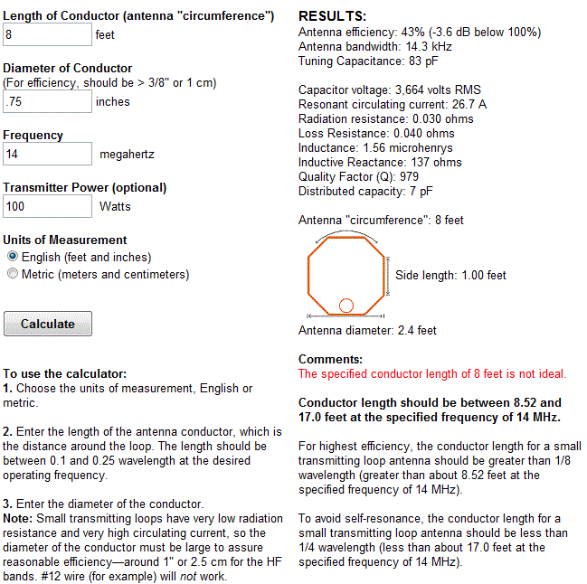
Using the 66pacific.com calculator we get the following:
The comments section informs us that, "The specified conductor length is not idea" and we can go on to read that, "To avoid self-resonance, the conductor length for a small transmitting loop antenna should be less than 1/4 wavelength (less than about 8.23 feet at the specified frequency of 29 MHz)."

Well, I don't want the wire in the loop to resonate by itself, its designed to resonate in combination with the capacitor. Lets make the loop 8 feet in circumference and while I'm at it I'll make it out of 3/4 (0.75) inch copper pipe for better conductivity.

Lets see what we have now:
Well, that seems to have fixed the self resonance issue and we've managed to bump up the antenna efficiency to 91% from 82% ... not a huge increase ( About 0.5 dB) so I could use either diameter copper tube in this case. Everything looks good so far!

How about the 20M band, at 14 MHz how do things look?
So, the specified conductor length is not ideal but the comments section says were under the 1/4 wavelength at 17 feet. What is also tells us is that, "For highest efficiency, the conductor length for a small transmitting loop antenna should be greater than 1/8 wavelength (greater than about 8.52 feet at the specified frequency of 14 MHz)." 

That is OK, we know that the MLA is going to be less efficient somewhere in its range and the suggestion of 8.52 feet is close enough to our 8 feet we can ignore it. The 42% efficiency is not the greatest but -3.6dB is about half an S-Unit down so I'll live with that.

Just for fun I changed the copper pipe back to 1/4 inch and the efficiency dropped to 20% (-7 dB) so I think I'll stick with 3/4 inch. It makes more of a difference at lower frequencies since more current is flowing through the loop!

In order to tune the loop between 14MHz and 29MHz we look at the Tuning Capacitance value in the last two calculations above. At 29 MHz the tuning capacitance required is 19 pF and at 14 MHz it is 83 pF. 
This is well within the capacitance range of a normal air variable capacitor and in fact a larger capacitor with a maximum capacitance of 160 pF would allow you to reach the 30M band with reduced efficiency. 

Its important however to look at the voltage across the capacitor in our last two examples. At 29 MHz we'll see a Capacitor voltage of 2,562 volts RMS and at 14MHz we'll see a Capacitor voltage of 3,664 volts RMS.

What does this mean? In order to know what kind of capacitor would be best we need to know the absolute maximum voltage it will have to withstand before it arcs between the closest conductors. If the voltage is high enough it will 'leak' between the plates of the capacitor by breaking down the air between them and directly passing an electric current ... we don't want this to happen.

The breakdown voltage of air is around 3000V per milimeter (39/1000 of an inch = 1 mm). The voltage above is shown as RMS (Useful for power calculations) but we need to know the peak value which is higher and determines the maximum voltage. The peak voltage = RMS x 1.414 or 3664 x 1.414 = 5181 V peak. 

A peak voltage of 5181V will require a minimum spacing of 1.7 mm (peak voltage / breakdown voltage per mm) between the closest conductors in the capacitor. That would rule out an old air spaced variable capacitor from a vacuum tube radio but you could still use a wide spaced variable capacitor from an antenna matching unit or transmitter. A vacuum variable capacitor would be great (watch the minimum capacitance) or a home-made capacitor would also be fine provided you checked the breakdown voltage of the insulating material.

What if all you have is a capacitor with insufficient plate spacing for that voltage? If you reduce the output power to 35W then the voltage across the capacitor will decrease to 2168 V RMS which is 3066 V peak( 2168 x 1.414) This voltage requires a 1 mm plate spacing which is easily achievable with surplus capacitors. At QRP power levels (5 W) the voltage falls to 1160 V peak and requires only 0.39 mm between the plates, suitable for practically any variable capacitor!

The value of 3000V / mm is only an approximation and if possible use a capacitor rated for a higher voltage than you expect to run to prevent damage to your radio. Modern rigs have great protections circuits but they shouldn't be relied on.

Next post I'll cover building the loop and coupling it to your transceiver. Hopefully you found this information useful and if there are mistakes or inaccuracies you'll drop me a line and set me right.

Friday, February 17, 2012

DIY Magnetic Loop Antenna - Part 1

Do you live in a neighborhood with a restrictive antenna policy and despair of having a useful HF antenna?

Can you solder or know someone who can?

A magnetic loop antenna may be the answer and they are not as difficult to build as you might think. Like getting on the air for the first time or taking your license exam there is a certain amount of uncertainty when you first approach magnetic loop antennas, there are a few new ideas to grasp. However, thanks to other hams like Steve AA5TB there are tried and tested designs, calculators & building methods that are known to work and that you can follow.

At the heart of every radio and MLA (Magnetic Loop Antenna) is the resonant circuit. The combination of an inductor (a wire has inductance, but a coil of wire has more) and a capacitor (two conductors separated by an insulator) in a circuit will resonate or 'ring' at a certain frequency. Sound vibrations at a certain frequency can cause a piano string to vibrate in sympathy and a vibration of the correct radio frequency will cause a resonant circuit to electrically vibrate in sympathy.
Since there is no such thing as a free lunch, the sacrifice you make with a MLA is that it needs to be re-tuned whenever you change frequency on your transceiver. The frequency range over which it is resonant is very small, typically only a few hundred kilohertz at the most.

The materials you can get your hands on is going to decide the capabilities of your MLA. Ideally you'll have a loop made from a conductor with very low resistance (usually copper) and a capacitor that can handle high voltages. A variable capacitor is required if you want to use your antenna on multiple frequencies but you can use or make a fixed capacitor if you operate on one frequency, for Eg PSK31.


A MLA calculator like the Excel spreadsheet from Steve AA5TB or this web page from 66pacific.com will help you to decide what size components you'll need to make your antenna.

The four pieces of information required are:

  1. What frequency or frequencies do you wish to transmit on?
  2. How large do you want the loop to be (It should have a circumference less than 10% of the design frequency wavelength, both calculators help you figure this out)
  3. The diameter of your conductor (Three quarter inch (0.75 inch) copper pipe is a good start)
  4. How much power you want to use (The voltage across the capacitor is proportional to the input power to the MLA)
A MLA of a certain circumference will be more or less efficient based on the frequency you transmit at. It is worth changing the loop size in the calculator to get the best efficiency possible in your favorite band. 
For example, my 30-10 Meter loop is 8.5 ft in circumference and 23% efficient at 10.1Mhz but 91% efficient at 28Mhz. This represents a difference of about 6dB or 1 S-Unit.

The diameter of the conductor determines its resistance and this becomes important due to the large current flowing through the loop. Large diameter copper pipe is better since the radio frequency current flows primarily on the outside of the conductor rather than the core. Typical 3/4 inch plumbing pipe is a good balance between low resistance and weight, Heliax coax is good for portable antennas where the loop has to be rolled up into a compact space.

Probably the most problematic part of the MLA is the tuning capacitor. While everything else can be found in your junk box or on a shelf at the local hardware store the capacitor takes a little more digging. Ideally it should be variable from a minimum to a fairly high capacitance (0-300 pF would be good) it should also be able to withstand high voltages. If you are planning to run 100W then you could expect at least 4000 volts across the capacitor. This is not as bad as it sounds as it takes 3300 volts to jump just 1mm or .04 of an inch.

Ideally you could purchase a vacuum variable capacitor, the Rolls Royce of high voltage variable capacitors. You would expect to pay anywhere from $100 up when buying a 10 - 500 pF unit on Ebay and a LOT more if you buy new. If that is the way you want to go then great, you're all set. If not then read on ...

There are several alternatives to the vacuum variable capacitor that will work almost as well. The primary concern now becomes resistance and plate separation. For QRP power levels you can use the tuning capacitors from old vacuum tube radios, the type that have a set of fixed metal plates and a set of moving plates that mesh into them.
For higher power there are two other types of capacitor that are suitable. 
One is the split-stator capacitor, so called because each terminal of the capacitor is connected to a stator that is electrically isolated from the other and the frame. The rotors and shaft form the rest of the circuit so there is very low resistive loss and no sliding contacts.
The other type is called a butterfly capacitor due to the shape of the rotor plates. In this type the stator plates are placed opposite each other with the butterfly rotor in between. When each of the butterfly "wings" are fully meshed between the stator plates the capacitor is providing maximum capacitance, when rotated 90 degrees the wings are completely un-meshed and the capacitor is providing minimum capacitance. Because of the construction of butterfly capacitor there is a higher minimum capacitance that should be noted when planning the frequencies your loop will cover.
If all else fails then you can construct your own variable capacitor. The idea is to have two conductors separated by an insulator, the larger the area of the conductors and the better the insulator the higher the capacitance. Sliding metal plates, trombones of copper tube and even Coke cans have been used as variable capacitors.

A fixed capacitor can be created out of coaxial cable if you intend to operate on one frequency and a table of approximate capacitances for different types of coax is included here, click to enlarge the table below.

You can cut a length of coax a bit longer than the length suggested by the table above and trim it to frequency once it is attached to the loop. Make sure there are no stray pieces of braid between the shield and the center conductor as the voltage rating is determined by the spacing of the two closest conductors.

Part two of this post will continue with calculating the antenna dimensions and performance.

One important thing to remember ... If you don't have access to the best materials then use what you have and improvise. If you don't have copper pipe then use coax or heavy wire. If you don't have a high end variable capacitor then use what you can find and keep the power levels QRP. The only antenna that is a complete failure is the antenna you never get around to building.

Friday, January 13, 2012

An oscilloscope clock - Recycling vintage equipment without destroying it.

As a fan of vintage electronics, and vintage technology in general,  I love to see things being re-used rather than being dumped in the trash. This has the very desirable effect of preventing sometimes toxic chemicals from being released into the environment and reduces the demand for new parts that can also involve toxic chemicals during their manufacture.

The only downside to this recycling is that frequently the original function of the equipment is lost so I was pleased to see this creation from Bob Alexander. He has combined one of the oldest types of test equipment with some of the newest microprocessor based devices to bring us a Oscilloscope Clock that still functions as an oscillloscope!

Heathkit oscilloscope with AVR Oscilloscope Clock module
Bob ran into some problems while installing the AVR Oscilloscope Clock Module but was able to invert the horizontal output from the clock module before feeding it into the scope. To read about his build in detail have a look at : An Oscilloscope From the Trash

A small modification to the rear panel to allow setting the clock and switching between clock and scope.
Check the video below for a demonstration of the Sparkfun AVR Oscilloscope Clock Module in action on a significantly newer oscilloscope.

Monday, January 9, 2012

PACO C-25 Capacitor Tester

I recently attended the Houston Vintage Radio Association post holiday dinner and participated in the auction held after the meal. It was a great evening and if you have any interest in vintage radio I would suggest getting in touch with the HVRA and becoming a member.
Among other things I walked away with at the end of the evening was a PACO Model C-25 capacitor tester.

The PACO C-25 differs from my Healthkit IT-22b in that it tests both regular and electrolytic capacitors as well as using a 40Mc oscillator to enable a rough measure of capacitance using a bridge circuit.
Most of the time, with vintage vacuum tube equipment, capacitor values need only be "in the ballpark" to function perfectly so a high degree of accuracy is not required. For more accuracy I have a Heathkit impedance/capacitance bridge if required.
I have my doubts how accurate the tester would be when measuring capacitance "in circuit" but otherwise it looks to be a very useful bit of kit!
The users manual should be available here and the circuit diagram is shown below.


Friday, January 6, 2012

More cheap power supplies ...

Looks as though more folks have been putting "bargain" power supplies to the test and finding them wanting. This time it is a 5 volt USB power supply purchased in the UK that fails to deliver its advertised load.

At 560mA load the voltage has already fallen below 3 Volts, a far cry from its rated 1 Amp!
As most power supplied are simply featureless black boxes it would be nice to be able to rely on the specifications stated on the outside ... sadly you can't as the video below shows.

Thursday, January 5, 2012

Winter Field Day and generators

With Winter Field Day coming up some radio operators may be running your stations using gas/petrol generators. While you can just drop the generator down outside and start it up you really should, for safety, have a ground rod set into the earth.
Although the system below does have a ground rod placed in the earth I'll leave it to you to discovery why it is not going to be very effective ...

Not the right way to ground a generator system, "A" for effort though.

Monday, January 2, 2012

Deathrays and the garage home-brewer

In days past home-brewers would often be at the forefront of new and developing technologies. Apple Computer got their start in a suburban garage, Marie Curie refined radium in little more than a garden shed and the founders of Hewlett Packard worked out of a home garage in Palo Alto.

Unfortunately we moved away from encouraging kids to "tinker" in the garage and instead we've supplied ready made entertainment in the way of game consoles, demographically targeted TV and an endless series of extra-curricula activities ... all ultimately aimed at preventing boredom and keeping kids busy.

To see some impressive tinkering, take a look at this great build from Teravolt.org. Its certainly something that could be dangerous if used incorrectly but the assumption that something is unsafe unless proved otherwise and the knowledge to know the difference is sometimes better that relying on a commercial manufacturer's assurance that everything is ok ... because sometimes it isn't.

X-Ray Machine from Teravolt.org
I don't think well raised kids will take to the streets in rampaging mobs if they are allowed to become 'bored' and I think there is the possibility that through their inventiveness they will discover and create things we haven't even imagined. Given the tools, basic education & a measure of respect we could see more garage pioneers in the coming years. While I understand the value of robot kits and 'following directions' I am more enthusiastic about the Maker movement and the great selection of micro-controllers and electronic building blocks they have created.

Looking through a hard-drive using the Teravolt.org X-Ray source

Thursday, December 22, 2011

Preserving the past - Australian built broadcast transmitters

Arguably some of the best looking radio equipment was produced in the 50's and 60's when art-deco motifs, streamlining and other elements of design made their way onto consumer and even industrial electronics.
Unlike modern times, when cost is the only consideration, designers and engineers took the time to ensure that their creations looked good as well as being functional and long lasting. It was worth taking time over the placement of meters, switches & panels, even if it did mean that the final product cost a few dollars more to manufacture.
Amalgamated Wireless (Australasia) or AWA produced an extensive range of home and commercial equipment in the 60s and many vintage radio collectors have examples of AWA radio receivers in their collections. The larger equipment like broadcast transmitters takes an extra special effort to preserve as their large size, demanding power requirements and the specialized knowledge required to maintain them presents a barrier for all but the most dedicated enthusiasts.
We are fortunate then that Don Bainbridge has taken up the challenge and preserved a remarkable collection of Australian built broadcasting equipment and maintains much of this equipment in operational order. The YouTube video below and his website linked here offer a rare glimpse into the world of vintage high powered broadcast equipment before plastic took over and economical design stripped away the chrome and pinstripes.

Wednesday, April 27, 2011

Alternate method of erasing CDs

Sure, anyone can grab a screwdriver and scratch the top off a burnable CD, making it unreadable for all but the most determined hackers ... but to REALLY do the job properly requires a bit more equipment.

Watch how this high voltage hell raiser from across the pond gets the job done: